
I've taken the first step in personalizing my new Transit. It's going to be my daily driver, and, I need to be able to transport a 14-foot kayak, INSIDE, either for local day trips, or for away trips, once I'm set up for camping.
For 15 years, I've carried a kayak on an elevated rack, over my pickup bed. I will happily give up the elevated storage, especially with moving to high-roofed (MR Transit) van. As I get older, floor level kayak storage will be better, and, there are other advantages to having it indoors. My 16 and 17-foot kayaks have sat unused for 2 years, as I had already favored the 14-footer -- a Dagger Alchemy -- for all-around fun.
So, 11 1/2 foot cargo box, 14-foot boat. I needed the space under the passenger seat, but, I did not want to completely remove the seat. I needed to make a convertible seat base. Fortunately, my kayaks are NOT of the chunky sit-on-top variety. In the photos you will see my 13 1/2 foot "dog boat," the widest of my kayaks. The width fit is very close with this mod.
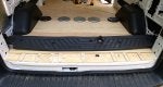
You'll see the seat is removed, along with the hydraulic bottle jack. The jack mounting bracket was held down with the 3 too-long bolts in the center area. I later cut those bolts to a shorter length, rather than remove them completely. I will put acorn nuts on them, for safety and possible future use.
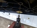
The non-moving base parts, held down by the original mounting bolts. Primary material is 1.25 inch, 14 gauge square tubing. Heavier base angle is 2 inch by 3/16 inch.
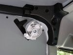
The moving parts, during a fitting. I made lift of about 7 1/4 inches from normal position. That's an inch more than I thought I needed, to allow for the thickness of a plywood or other floor in the cargo area.
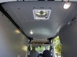
Success - view from behind, and side view of the seat raised above the kayak bow.
Space under the seat is pretty clear, except for that one cross-piece for the seat adjuster. It turns out I would have been fine with an inch less lift. There are 60 pieces that I had to make, plus 8 bronze bushings and 2 hitch pins that were purchased at Lowes.
No, the seat is not to be used when it's raised to accommodate a kayak.
No, I'm not a professional welder.
Yes, I still need to clean it up and paint it.
No, my setup might not get the same crash test rating as the Ford engineered pedestal. But, it will rarely be used by another person.
While I have your attention, please see my next post, below. Concept questions I need to resolve, before proceeding with my light camper van build.
For 15 years, I've carried a kayak on an elevated rack, over my pickup bed. I will happily give up the elevated storage, especially with moving to high-roofed (MR Transit) van. As I get older, floor level kayak storage will be better, and, there are other advantages to having it indoors. My 16 and 17-foot kayaks have sat unused for 2 years, as I had already favored the 14-footer -- a Dagger Alchemy -- for all-around fun.
So, 11 1/2 foot cargo box, 14-foot boat. I needed the space under the passenger seat, but, I did not want to completely remove the seat. I needed to make a convertible seat base. Fortunately, my kayaks are NOT of the chunky sit-on-top variety. In the photos you will see my 13 1/2 foot "dog boat," the widest of my kayaks. The width fit is very close with this mod.
You'll see the seat is removed, along with the hydraulic bottle jack. The jack mounting bracket was held down with the 3 too-long bolts in the center area. I later cut those bolts to a shorter length, rather than remove them completely. I will put acorn nuts on them, for safety and possible future use.
The non-moving base parts, held down by the original mounting bolts. Primary material is 1.25 inch, 14 gauge square tubing. Heavier base angle is 2 inch by 3/16 inch.
The moving parts, during a fitting. I made lift of about 7 1/4 inches from normal position. That's an inch more than I thought I needed, to allow for the thickness of a plywood or other floor in the cargo area.
Success - view from behind, and side view of the seat raised above the kayak bow.
Space under the seat is pretty clear, except for that one cross-piece for the seat adjuster. It turns out I would have been fine with an inch less lift. There are 60 pieces that I had to make, plus 8 bronze bushings and 2 hitch pins that were purchased at Lowes.
No, the seat is not to be used when it's raised to accommodate a kayak.
No, I'm not a professional welder.
Yes, I still need to clean it up and paint it.
No, my setup might not get the same crash test rating as the Ford engineered pedestal. But, it will rarely be used by another person.
While I have your attention, please see my next post, below. Concept questions I need to resolve, before proceeding with my light camper van build.